


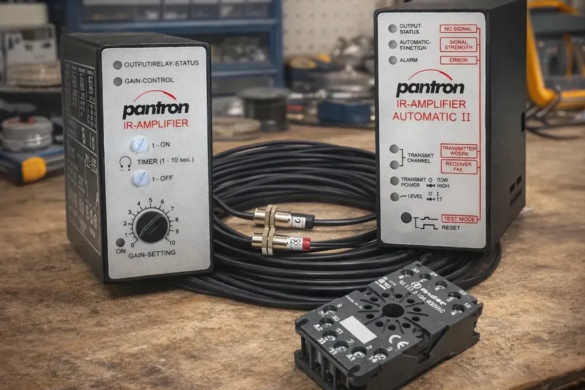
Photoelectric sensors are among the most reliable components in any industrial automation system, but they do occasionally fail or behave unexpectedly. When a photoelectric system stops functioning, a systematic troubleshooting approach will identify the root cause far more efficiently than random component replacement. This guide covers the diagnostic steps for the most common failure modes — and provides the methodical approach that separates a quick resolution from an extended troubleshooting session.
Before You Start: Know What You Are Working With
The first step in any troubleshooting process is to understand the system being diagnosed. Photoelectric sensors come in several configurations, and the diagnostic approach varies accordingly.
Through-beam (opposed-mode) — a separate transmitter and receiver face each other across a gap. The output changes when an object breaks the beam between them. This is the most powerful and reliable configuration.
Retro-reflective — transmitter and receiver are housed together in a single unit. The beam bounces off a separate reflector and returns to the receiver. An object passing between the sensor and the reflector breaks the beam.
Diffuse proximity — transmitter and receiver are in the same housing. The sensor detects objects by the reflection of the beam off the target surface. No separate reflector is required.
Identify which type is in use before beginning. If the part number is still legible on the sensor body, locate the manufacturer's data sheet online. Having the data sheet eliminates much of the guesswork around voltage requirements, output type, adjustment procedures, and normal operating behavior.
Step 1: Define the Problem
Before touching anything, clearly define the failure mode. The symptom determines the most likely cause:
- Output is always active (on), even with no object present — the sensor is reporting detection when nothing is there
- Output is never active, even when an object is clearly in the sensing zone — the sensor fails to detect its target
- Output is intermittent or flickering — the sensor is unreliable; sometimes it works, sometimes it does not
- Problem occurs only at a certain time of day — suggests ambient light or temperature as a contributing factor
- Problem appeared suddenly after the system was working — suggests a physical change (damage, contamination, misalignment) rather than a design issue
Step 2: Check for Environmental Influences
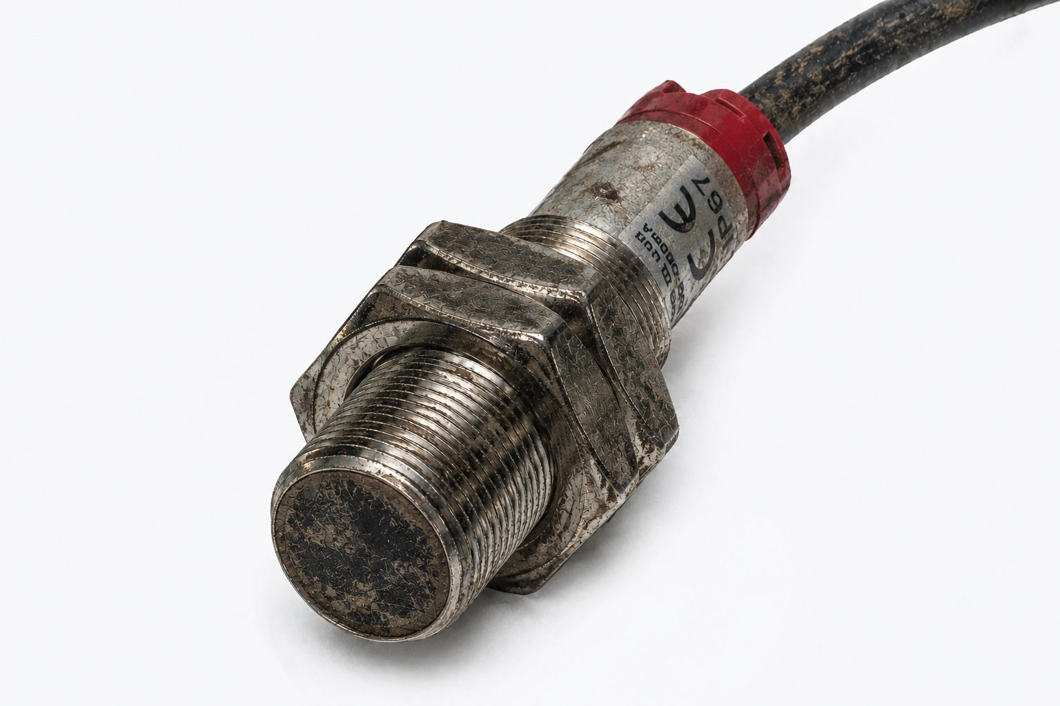
Environmental conditions are responsible for a large proportion of photoelectric sensor problems.
Contamination on the Lens Face
The most common cause of degraded sensor performance is a dirty lens face. Dust, oil mist, condensation, soap film, and other contamination accumulate on the optical surface over time and reduce the effective power of the infrared beam. A sensor that was working perfectly when clean may fail to detect, give intermittent outputs, or trigger without a target present once the lens is sufficiently dirty.
Inspect the face of every sensor and reflector in the system. Use a soft, lint-free cloth and a mild, non-abrasive cleaner to wipe the surfaces clean. Re-test after cleaning — this resolves a significant percentage of photoelectric sensor complaints.
Direct Sunlight on the Receiver
Sunlight contains infrared radiation. If the receiver photo eye is positioned in direct sunlight, the ambient infrared from the sun can saturate the receiver and prevent it from detecting the modulated infrared from the transmitter. This often manifests as a time-of-day failure pattern — the sensor works fine in the morning but fails in the afternoon when the sun angle changes.
The transmitter can typically be mounted in direct sunlight without issue, because the transmitter only emits — it does not receive. The receiver, however, should be shielded from direct sun exposure. Reorienting the sensor, adding a sunshade, or using polarizing filter attachments resolves most sunlight interference problems.
Electrical Interference
Sensors mounted near large motors, welding machines, variable frequency drives, or power cables can pick up electrical interference that causes false outputs. Verify that sensor signal wiring is run in separate conduit from power cables. Confirm that the sensor is properly grounded. If interference is suspected, try routing the sensor cable away from potential noise sources or replacing unshielded cable with shielded cable.
Step 3: Check Alignment

Misalignment is a leading cause of through-beam and retro-reflective sensor problems. If the transmitter and receiver are not aimed directly at each other (or at the reflector, for retro-reflective systems), the received signal strength will be reduced, leading to unreliable detection.
Use the string method for alignment verification: pull a length of string or wire taut between the two sensors so the string runs parallel alongside both sensor faces. If one sensor is parallel to the string and the other is not, misalignment is present. When re-aligning, adjust the transmitter only — there is no value in adjusting the receiver if the source of the beam is aimed incorrectly.
For sensors with a visible indicator LED (signal strength or alignment indicator), use that LED to confirm alignment by maximizing the LED brightness or achieving a stable ON state.
Step 4: Check Power Supply
An insufficient or absent power supply is easily overlooked but always worth verifying, especially when troubleshooting a system for the first time or after electrical work has been performed in the area.
Set a multimeter to the appropriate DC voltage range. Measure the supply voltage at the sensor connection point — not at the power supply terminal — to account for any voltage drop in the cable run. Confirm the measured voltage is within the sensor's rated supply range, which is typically 10-30 VDC for most industrial sensors. A supply that is within specification at the power supply but below the sensor's minimum at the sensor end due to undersized wiring is a real failure mode.
Checking for Infrared Beam Presence
For sensors using infrared light (invisible to the naked eye), use a smartphone or digital camera in video mode to verify the transmitter is emitting. Many camera sensors are sensitive to near-infrared light and will display the transmitter beam as a visible glow on the screen, even though it cannot be seen with the naked eye. Some cameras with night-vision modes (sometimes called Night Shot or Night Vision) are particularly effective for this purpose.
Step 5: Inspect Wiring and Connections
Physical wire problems — particularly at splice points and connector joints — are a common cause of intermittent sensor behavior.
Inspect every point where wires have been cut and reconnected. Wires simply twisted together, or connected with basic wire nuts in a wet or vibration-prone environment, are inherently unreliable. Proper splices should be soldered and covered with adhesive-lined heat-shrink tubing to create a mechanically strong and moisture-resistant connection. Corrosion at splice points is a common finding in systems that have been running for several years.
In through-beam systems, confirm that the transmitter and receiver are connected to the correct wires. Reversing these connections is an easily made installation error that prevents the system from functioning.
Step 6: Adjust Sensitivity
If alignment and cleanliness are confirmed and the system still does not detect reliably, the gain (sensitivity) setting may need adjustment.
- For a sensor that is not detecting objects it should detect — increase the gain. The beam may not have enough reserve power to reliably trigger the receiver when the target is present.
- For a sensor that is triggering when no target is present — decrease the gain. Excess sensitivity may be causing the sensor to respond to distant objects, reflections, or environmental interference.
- For a sensor where objects pass through without breaking the beam — reduce the gain first. If the beam is extremely powerful, it may be reflecting around the object via surfaces in the environment. Also check whether the object passes close enough to the receiver end to fully interrupt the beam at the given sensitivity level.
Step 7: Use PVC Pipe to Narrow the Beam
If sensitivity adjustment alone does not resolve detection problems, particularly when the target is small or when environmental reflections are causing false detection, physical beam limitation can help. A short length of narrow-bore PVC pipe placed over the face of the transmitter narrows the outgoing beam to a tighter cone. The same technique on the receiver face narrows its field of view. This combination reduces the sensor's sensitivity to off-axis reflections and improves the precision of small-object detection.
When to Call for Support
If the above steps do not resolve the issue, contact the sensor manufacturer or your Pantron Automation representative directly. Have the following information ready:
- Sensor model and part number
- Supply voltage being used
- Sensing configuration (through-beam, retro-reflective, or diffuse)
- Description of the failure mode and when it occurs
- What troubleshooting steps have already been attempted
A manufacturer's application engineer can often diagnose problems remotely based on this information and recommend a path to resolution quickly. Documentation from a systematic troubleshooting process — rather than simply "it stopped working" — makes that conversation far more productive.