


The pneumatic air hose switch is one of the oldest vehicle and object detection technologies in use. Drivers old enough to remember full-service gas stations will recall the familiar bell that sounded when a car pulled up to the pumps — triggered by the front tires rolling over a rubber hose stretched across the driveway. That same technology, while conceptually simple, is still in use at many businesses today. And it still carries the same limitations it always has: mechanical wear, misalignment, and unreliable performance over time.
Industrial-grade infrared photoelectric sensors provide a modern, non-contact alternative that eliminates these limitations while delivering superior reliability and easier maintenance.
How Air Hose Systems Work
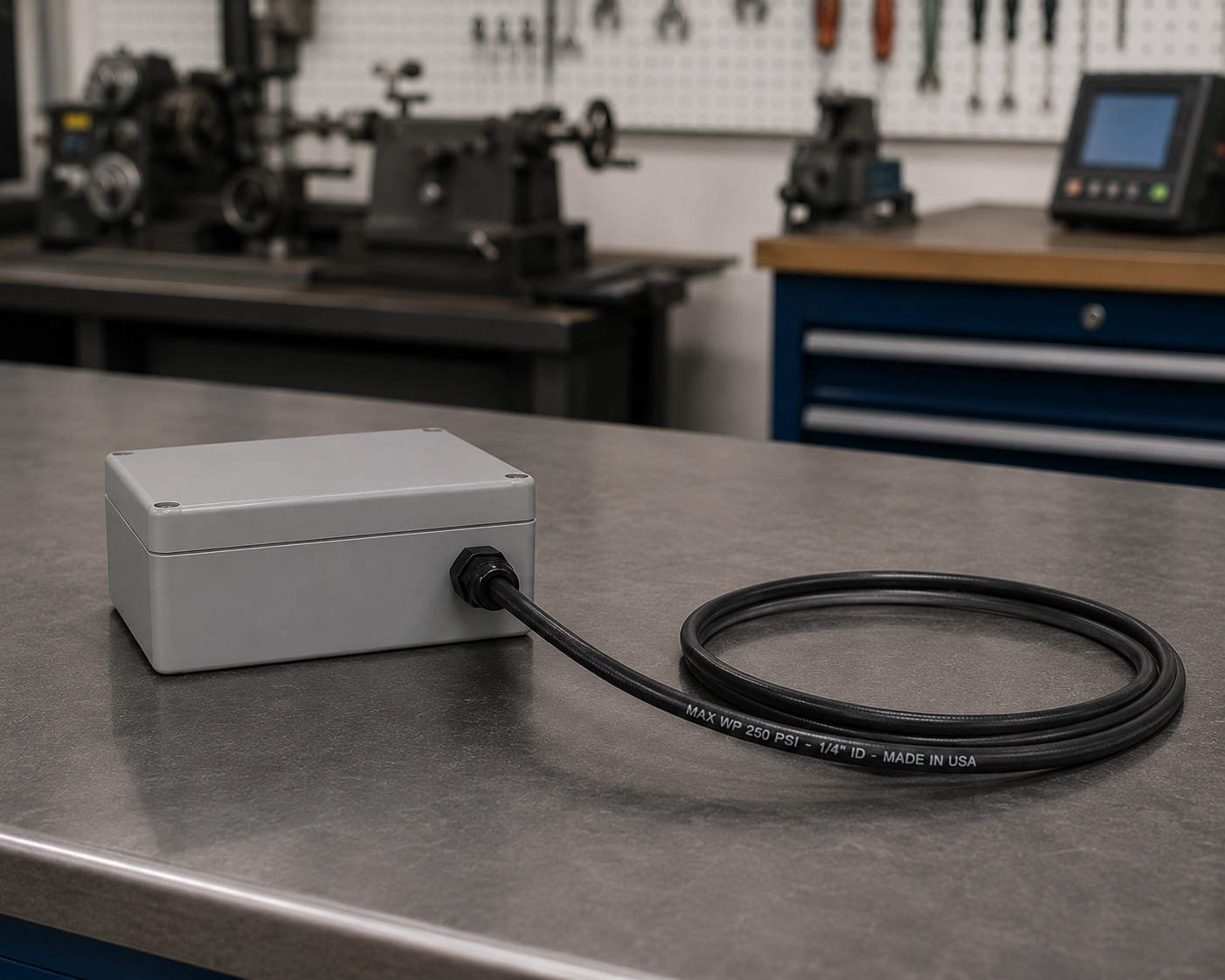
An air pressure hose switch operates on a straightforward mechanical principle. A rubber hose is stretched across a lane of traffic, a doorway threshold, or any path where object detection is needed. The hose is connected at one end to a pneumatic switch. When a vehicle tire — or any sufficiently heavy object — rolls over or presses down on the hose, the compressed air rushes to the switch end and actuates a mechanical switch. This switch closure can trigger almost any electrical device: a bell, a counter, a gate controller, or a traffic signal.
Common applications include:
- Traffic counting and demographic studies
- Vehicle detection at parking facilities and drive-throughs
- Automatic door and gate activation
- Queue management at service facilities
- Drive-through lane monitoring
Despite its simplicity, the air hose system has inherent weaknesses. The rubber hose degrades under UV exposure, automotive fluids, and repeated mechanical compression. The pneumatic switch contains moving parts that wear out. The hose can be displaced from its intended position by vehicle traffic, maintenance activities, or weather. And the entire system requires periodic recalibration and replacement.
The Case for Photoelectric Sensors
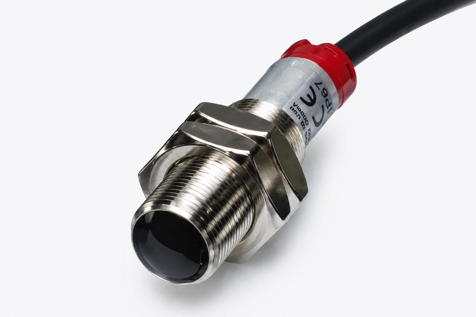
Industrial infrared photoelectric sensors solve every significant limitation of the air hose approach. By detecting vehicles without any physical contact, they eliminate the mechanical wear that eventually compromises every air hose installation.
No moving parts — an infrared photoelectric system consists of a transmitter that emits a modulated infrared beam and a receiver that monitors the presence of that beam. When the beam path is interrupted by a vehicle or other object, the receiver output changes state. There is nothing to compress, nothing to flex, and nothing to wear out from repeated actuation. The only maintenance required is occasional cleaning of the sensor faces and periodic alignment verification.
Non-contact detection — vehicles never touch the sensors. This eliminates the mechanical stress that degrades air hoses and prevents the false triggers that occur when a hose is shifted by traffic. It also means the sensors can be positioned where vehicles cannot damage them — mounted on posts, walls, or overhead structures well away from the driving surface.
Weather resistance — industrial photoelectric sensors rated for outdoor use are sealed against moisture, dust, and temperature extremes. They perform reliably in rain, snow, and extreme heat without the rubber degradation that limits outdoor air hose installations.
Long service life — industrial-grade photoelectric sensors are designed for years of continuous operation. In contrast to air hose systems that may require hose replacement every season, a well-selected and properly installed photoelectric sensor system can operate for years without replacement.
Making the Transition
Replacing an air hose detection system with a photoelectric sensor system is straightforward. The key is matching the electrical interface of the new system to the device being controlled.
Choosing a Controller with Relay Output
Select a photoelectric sensor system that includes an amplifier or controller with a built-in mechanical relay output. A relay output functions identically to the mechanical switch in the old pneumatic switch — when the sensor triggers, the relay closes, completing the circuit to whatever device is connected. This makes the transition as simple as disconnecting the old pneumatic switch and connecting the relay output of the new photoelectric controller in its place.
Many photoelectric controllers also offer selectable output modes. A normally closed output mode — where the relay is closed when the beam is present and opens when the beam is broken — can replicate the behavior of some pneumatic switch configurations. A normally open output mode closes when the beam is broken. Select the mode that matches the logic expected by the connected device.
Sensor Configuration
For vehicle detection in lanes or driveways, the through-beam (opposed-mode) configuration is recommended. In this configuration, the transmitter is mounted on one side of the lane and the receiver is mounted directly across on the other side. The infrared beam projects across the lane at the appropriate height to intersect any passing vehicle.
Alternatively, if through-beam mounting is not possible due to the physical layout — for example, in a driveway where mounting on both sides is not practical — a diffuse proximity configuration places both sensors on the same side and detects objects by the reflection of the infrared beam off the vehicle surface. Diffuse mode has a shorter effective range and is somewhat more sensitive to target surface reflectivity, but it provides a practical solution where through-beam installation is not an option.
A retro-reflective configuration is another option that uses a reflector on the opposite side of the lane. The transmitter and receiver are housed together in a single unit on one side, and the beam bounces off the reflector back to the receiver. This can be easier to wire than a true through-beam setup while still providing better performance than diffuse proximity mode.
Loop Detectors as an Alternative
For applications where the detection must be embedded in the roadway surface — such as traffic signal control, parking gate management, or high-security entry control — inductive loop detectors combined with in-ground wire loops provide a complementary technology. Loop detectors sense the presence of a vehicle by detecting the change in inductance caused by the vehicle's metallic mass passing over the embedded wire loop. Pantron Automation distributes Bircher Reglomat loop detectors for exactly these applications.
Practical Installation Tips
- Mount sensors where vehicles cannot strike them — the primary advantage of non-contact detection is lost if the sensors are positioned where vehicles can hit them. Use mounting locations on posts, building walls, or overhead structures at a safe distance from the vehicle path.
- Protect cable runs — route all wiring in conduit, especially in areas where vehicles could drive over cables. Use outdoor-rated conduit and waterproof fittings at all junction points.
- Select appropriate sensing range — choose sensors with a range that comfortably spans the full width of the lane or area being monitored, with margin to spare.
- Adjust sensitivity after installation — once the sensors are mounted, adjust the gain setting on the amplifier to the point where vehicles reliably trigger the output while small debris, birds, and casual foot traffic do not. Getting this balance right for the specific application is important.
- Test with representative vehicles — include the range of vehicle types expected at the installation in your testing, from compact cars to large trucks and vans if applicable.
The transition from an air hose detection system to industrial infrared photoelectric sensors is a smart investment that pays for itself quickly in reduced maintenance costs, improved reliability, and the elimination of downtime caused by hose failures and pneumatic switch wear.